[ Overview |
lucernhammer MT |
Serenity |
Onyx |
Galaxy |
Orion |
Lyra |
Emerald |
Sapphire ]
[ lucernhammer RCS Server |
Benchmark Data |
FAQ |
Ordering Information ]

[ Overview |
lucernhammer MT |
Serenity |
Onyx |
Galaxy |
Orion |
Lyra |
Emerald |
Sapphire ]
[ lucernhammer RCS Server |
Benchmark Data |
FAQ |
Ordering Information ]
EMCC Three-Dimensional Benchmark Targets
On this page are presented simulated RCS data for the three-dimensional EMCC benchmark radar targets that were described and measured in the following papers:
A. C. Woo, H. T. G. Wang, M. J. Schuh, and M. L. Sanders, "Benchmark radar targets for the validation of computational electromagnetics programs," IEEE Antennas Propagat. Magazine, vol. 35, pp. 84–89, February 1993.
and
A. Greenwood, "Electromagnetic Code Consortium Benchmarks," Tech. Rep. AFRL-DE-TR-2001-1086, Air Force Research Laboratory, December 2001.
The objects considered from the first paper are the ogive, double ogive, cone-sphere, cone-sphere with gap, and the NASA almond, and those from the second are the cube and prism. The first four objects are bodies of revolution (BORs), and so we will simulate each using Serenity and Galaxy. The NASA almond, cube and prism we simulate using only Serenity. Detailed descriptions and dimensions of each object can be found in the referenced papers, as well as The Method of Moments in Electromagnetics, Third Edition.
All the three-dimensional radar targets are considered to be perfectly electrically conducting (PEC).
We note that in the RCS range, the objects were positioned on a rotating platform in the xy plane. Therefore, facet models constructed for Serenity have an x-axis alignment. Boundary files for Galaxy have implicit z-axis alignment, and so its computed vertical (theta) and horizontal (phi) polarizations are mapped to measured horizontal and vertical polarizations, respectively.
In Serenity we use the Adaptive Cross Approximation (ACA) mode in each case, except for the EMCC Prism at 9.2 GHz, where the Multi-level Adaptive Cross Approximation (MLACA) mode is used. This reduces the memory requirement at the expense of increasing the run time.
Original Rhinoceros 3D models are provided for each object, however these may contain just the bounding curve, or a portion of the 3d surface, etc. If you want to construct a mesh from these models, additional work may be needed, such as revolution around an axis, as well as exporting into a meshing tool of choice. All meshes below were made using Altair Hypermesh.
All calculations were performed on a Dell Precision T7900 workstation running Ubuntu Linux, with dual twelve-core Intel Xeon CPUs (E5-2690 v3) at 2.6 GHz with 256 GB of RAM, and dual NVIDIA GTX 1080Ti GPUs, each with 12GB of onboard RAM. Serenity utilizes both GPUs.

|

|
| Ogive Dimensions (Inches) | Ogive Facet Model Detail |

|

|
| Ogive VV RCS | Ogive HH RCS |

|

|
| Double Ogive Dimensions (Inches) | Double Ogive Facet Model Detail |

|

|
| Double Ogive VV RCS | Double Ogive HH RCS |

|

|
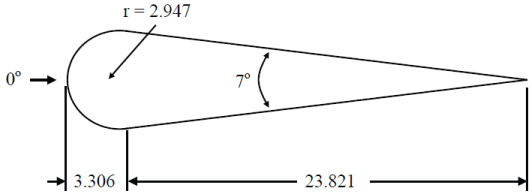
| Cone-Sphere Dimensions (Inches) | Cone-Sphere Facet Model Detail |

|

|
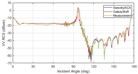
| Cone-Sphere VV RCS | Cone-Sphere HH RCS |
The agreement for both polarizations is fairly good at all angles, although there is some disagreement at angles above 120 degrees. As the RCS at these angles is much lower, this is likely due to the noise floor in the measured data.
The side specular in the measured data near 100 degrees is noticeably broader and of lesser amplitude than in the simulated data. The reason for this difference is not known, and was not mentioned in the original paper.
The EMCC cone-sphere with gap is identical to the cone-sphere except that a square groove of depth 1/4 inch is cut into the target near the cone-sphere junction point (3.306 inches from the left of the figure).

|
| Cone-Sphere Facet Model Detail |

|

|
| Cone-Sphere With Gap VV RCS | Cone-Sphere With Gap HH RCS |
The side specular in the measured data near 100 degrees is noticeably broader and of lesser amplitude than in the simulated data, as it was in the data for the cone-sphere. The reason for this difference is again not known, and was not mentioned in the original paper.

|

|
| NASA Almond Profile in xy plane | NASA Almond Profile in xz plane |

|

|
| NASA Almond Facet Model Detail in xy plane | NASA Almond Facet Model Detail in xz plane |

|

|
| NASA Almond VV RCS, 7.0 GHz | NASA Almond HH RCS, 7.0 GHz |

|

|
| NASA Almond VV RCS, 9.92 GHz | NASA Almond HH RCS, 9.92 GHz |
Compared here is the RCS of the NASA almond at 7.0 and 9.92 GHz. The RCS computed by Serenity was lower than the measurements by approximately 1.5 dB across a large range of angles, and are adjusted by that amount in each figure. The difference in vertical polarization at 9.92 GHz is much greater than at other frequencies and polarizations, and the reason for this is not known. The authors in the original paper noted this difference with their own simulated data, and suggested the cause may have been the density of the unknowns (6 edges per wavelength) in the CAD model that was used. As our facet model here comprises a much greater density (about 13 edges per wavelength), the cause is likely due to something else.
Note that the facet file constructed for 9.92 GHz was used at both frequencies, as the denser model conforms to the underlying surface curvature to a better degree.
The EMCC cube is a high-precision conducting cube with sides of length 1 meter and axis-aligned faces. Monostatic observations are made in the xy plane at 0.43 and 1.3 GHz, for azimuth angles ranging from 0 to 360 degrees.

|

|
| EMCC Cube Facet Model Detail at 0.43 GHz | EMCC Cube Facet Model Detail at 1.3 GHz |

|

|
| EMCC Cube VV RCS, 0.43 GHz | EMCC Cube HH RCS, 0.43 GHz |

|

|
| EMCC Cube VV RCS, 1.3 GHz | EMCC Cube HH RCS, 1.3 GHz |
The EMCC prism has a base in the xy plane having dimensions shown below, and an overall thickness of 30.48 cm. Monostatic observations are made at 0.43, 1.3 and 9.2 GHz at an elevation of 10 degrees, for azimuth angles between -180 and 180 degrees.


|

|
| Prism Facet Model Detail at 0.43 GHz | `Prism Facet Model Detail at 1.3 GHz |

|

|
| EMCC Prism VV RCS, 0.43 GHz | EMCC Prism HH RCS, 0.43 GHz |

|

|
| EMCC Prism VV RCS, 1.3 GHz | EMCC Prism HH RCS, 1.3 GHz |

|

|
| EMCC Prism VV RCS, 9.2 GHz | EMCC Prism HH RCS, 9.2 GHz |
The comparison is fairly good at and near specular angles, but there is a fair amount of disagreement elsewhere, particularly near 180 degrees in azimuth. Comparisons in the original paper against results obtained from the Fast Illinois Solver Code (FISC), an MLFMA-based MoM solver, showed similar disagreements, the reasons for which are unknown.