
[ Overview |
lucernhammer MT |
Serenity |
Onyx |
Galaxy |
Orion |
Lyra |
Emerald |
Sapphire ]
[ lucernhammer RCS Server |
Benchmark Data |
FAQ |
Ordering Information ]

[ Overview |
lucernhammer MT |
Serenity |
Onyx |
Galaxy |
Orion |
Lyra |
Emerald |
Sapphire ]
[ lucernhammer RCS Server |
Benchmark Data |
FAQ |
Ordering Information ]
Bodies of Revolution
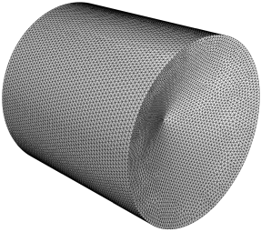
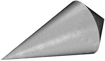
On this page are presented monostatic RCS data for a collection of conducting (PEC) bodies of revolution, each comprising one or more sections having the shapes of cones, cylinders and frustums.
For these test cases, the more relevant scattering effects will be first-bounce (specular) scattering, single and double diffractions, tip diffractions, and traveling wave effects. For the completely convex objects in the collection, these will be no multibounce scattering, and for the others, it should be minimal.
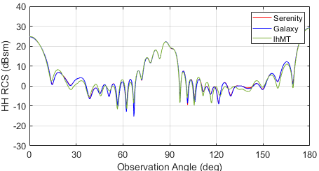
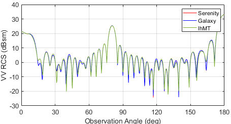
The outputs of Serenity, Galaxy, and lucernhammer MT will be compared for each target. Serenity and lucernhammer MT use the same facet files as inputs.
lucernhammer MT is configured to use facet-level physical optics (PO) for all first-bounce scattering. Multibounce via shooting and bouncing rays (SBR) is enabled only for the arrow cylinder target.
All the radar targets below are considered to be perfectly electrically conducting (PEC), and dimensions are in wavelengths. Zero degrees incident angle is defined as from the left in each figure. All models are constructed with their body axis aligned along the +z-axis.
Original Rhinoceros 3D models are provided for each object, however these may contain just the bounding curve, or a portion of the 3d surface, etc. If you want to construct a mesh from these models, additional work may be needed, such as revolution around an axis, as well as exporting into a meshing tool of choice. All meshes below were made using Altair Hypermesh.
All calculations were performed on a Dell Precision T7900 workstation running Ubuntu Linux, with dual twelve-core Intel Xeon CPUs (E5-2690 v3) at 2.6 GHz with 256 GB of RAM, and dual NVIDIA GTX 1080Ti GPUs, each with 12GB of onboard RAM. Serenity utilizes both GPUs.

|

|
| Arrow Cylinder Dimensions (Wavelengths) | Arrow Cylinder Facet Model Detail |

|

|
| Arrow Cylinder VV RCS | Arrow Cylinder HH RCS |
As the rear section of this object is slightly concave, shooting and bouncing rays (SBR) is enabled in lucernhammer MT. It is at incident angles above 120 degrees where the most disagreement is seen between the low and high-frequency codes.

|

|
| Cone Cylinder Dimensions (Wavelengths) | Cone Cylinder Facet Model Detail |

|

|
| Cone Cylinder VV RCS | Cone Cylinder HH RCS |

|

|
| Double Cone Dimensions (Wavelengths) | Double Cone Facet Model Detail |

|

|
| Double Cone VV RCS | Double Cone HH RCS |

|


|
| Flare Cylinder Dimensions (Wavelengths) | Flare Cylinder Facet Model Detail |

|
|
| Flare Cylinder VV RCS | Flare Cylinder HH RCS |

|


|
| Frustum Dimensions (Wavelengths) | Frustum Facet Model Detail |
|

|
| Frustum VV RCS | Frustum HH RCS |

|

|
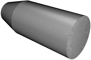
| Frustum Cylinder Dimensions (Wavelengths) | Frustum Cylinder Facet Model Detail |

|
|
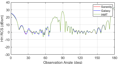
| Frustum Cylinder VV RCS | Frustum Cylinder HH RCS |

|


|
| Half Sphere Dimensions (Wavelengths) | Half Sphere Facet Model Detail |

|

|
| Half Sphere VV RCS | Half Sphere HH RCS |

|


|
| Long Conesphere Dimensions (Wavelengths) | Long Conesphere Facet Model Detail |

|

|
| Long Conesphere VV RCS | Long Conesphere HH RCS |

|

|
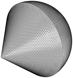
| Short Conesphere Dimensions (Wavelengths) | Short Conesphere Facet Model Detail |

|

|
| Short Conesphere VV RCS | Short Conesphere HH RCS |

|

|
| Thick Ogivedisk Dimensions (Wavelengths) | Thick Ogivedisk Facet Model Detail |

|

|
| Thick Ogivedisk VV RCS | Thick Ogivedisk HH RCS |
Of note here is the interesting behavior of the RCS as computed by lucernhammer MT for aspect angles close to 90 degrees. It is in this region where portions of the diffracting edge that circles the disk becomes shadowed; because the facet model comprises discrete triangles and straight-line edges, and a ray-tracer is used to determine the shadowing function, the edge diffracted RCS computed via PTD has a somewhat stair-stepped behavior. This effect is further amplified in the following test case (thin ogivedisk). These effects might be minimized by generating a separate edge file with a far greater level of discretization, or by computing the edge diffracted field by other means and adding it to the first-order PO field computed by lucernhammer MT. However, here we use the edge data "as-is" from the given facet model.

|

|
| Thin Ogivedisk Dimensions (Wavelengths) | Thin Ogivedisk Facet Model Detail |

|

|
| Thin Ogivedisk VV RCS | Thin Ogivedisk HH RCS |
In this case, the limitations of the high-frequency edge-diffracted field near 90 degrees incident angle is amplified even more from the previous case (thick ogivedisk). This demonstrates the inherent limitations in ray-tracing based high-frequency solvers, which are not limited to lucernhammer MT but found in others as well.